Sizing of Components
All ServicesAll components of a process plant need to be sized considering all possible operating conditions. The minimum requirements for the sizing of a component are the design pressure and the design temperature. In any case, however, additional characteristics need to be defined depending on the specific purpose of the component. In terms of it's dimensions, a component must neither be selected too small nor larger than necessary. Both cases, in their own way, can have a negative impact on the operation of the plant. Based on the sizing of the components the technical specifications will be created.
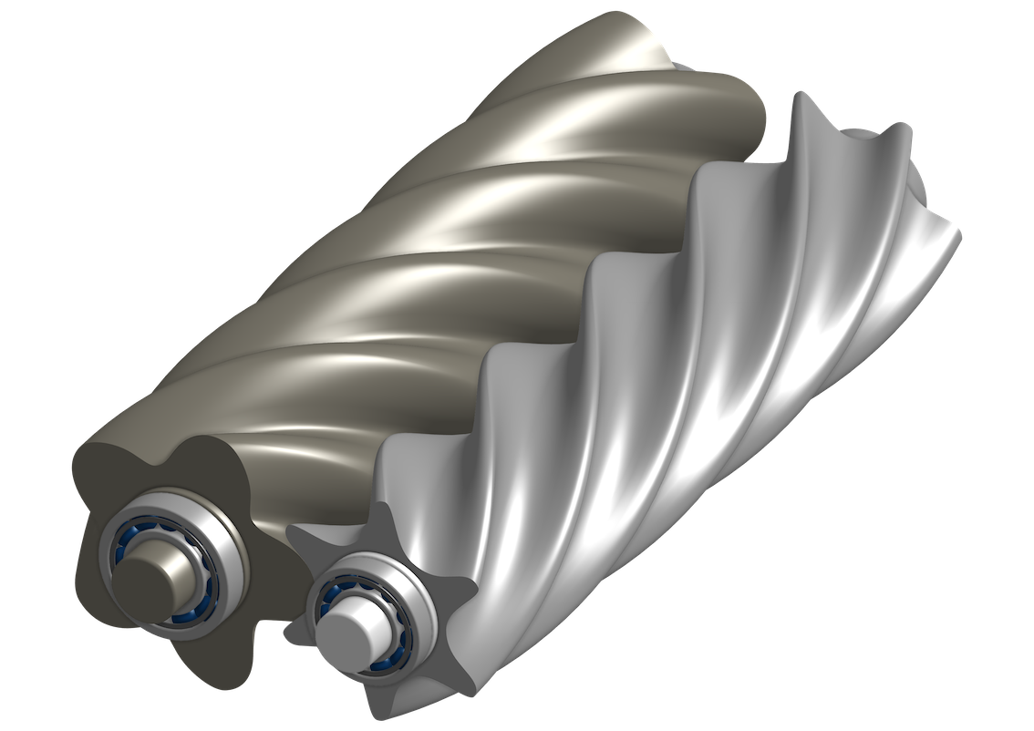
Compressors
In process plants compressors are used to compress process and service media. An often needed typical application is the supply of instrument air for the operation of pneumatic components, for example control valves. Among other things the selection of the proper compressor type depends on the flow capacity, the suction and discharge pressure, and the required purity of the compressed medium. As density changes with pressure deviations of the suction and discharge pressure have an impact on the flow capacity. If needed, an aggregate for oil separation is used after the compression stage in case that the medium can become contaminated with oil while passing through the compressor. As the dew point increases with increasing pressure, components of the compressed media can potentially experience condensation. For this reason, if ambient air is compressed to be used as instrument air, a drying process is used after the compression stage.
What we can do for you!
We evaluate the relevant operating cases for the sizing of each compressor.
We select the proper compressor type for the application.
We create the technical specifications for the procurement of the compressors from external suppliers.
We evaluate concepts for the economic cooling of the compressors using existing heat sinks.
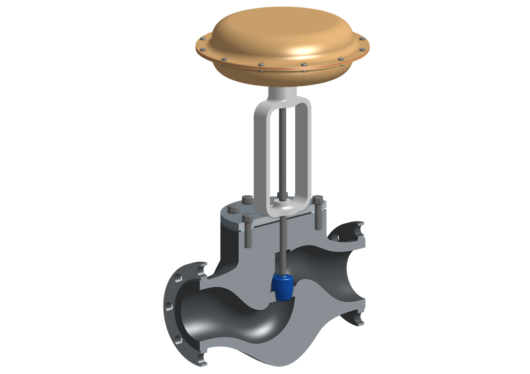
Control Valves
Control valves govern the flow of liquid and gaseous media within a process plant. They control pressure and temperature conditions, the fill level of vessels, or flowrates. The flow capacity of a control valve must be selected to match the corresponding process conditions. The control behaviour might become unstable and inaccurate if the flow capacity is too high. If it is too low the plant capacity might be reduced. A comparably inexpensive control valve with an insufficient flow capacity can have similar negative effects as a faultily sized, expensive compressor.
What we can do for you!
We evaluate the relevant operating cases for the sizing of each control valve.
We select the proper valve type for the application.
We identify the required Kvs-value and the control characteristic that is suitable for the application.
We create the technical specifications for the procument of the control valves from external suppliers.
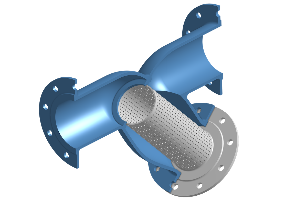
Filters and Strainers
Filters and strainers are used to separate solid particles from a process flow for further processing or to remove impurities from a process flow. The pressure losses occurring across filters and strainers depend, among other things, on the load level and can therefore vary significantly. In order to prevent damage to components downstream of filters and strainers, which are subject to a minimum allowed operating pressure, monitoring of the pressure loss might be necessary so that protective measures can be activated in case of excessively high values. Collected impurities need to be frequently removed from filters and strainers, either manually or by automated procedures.
What we can do for you!
We evaluate the relevant operatin conditions for the sizing of all filters and strainers.
We define measures to ensure that the pressure losses across filters and strainers neither negatively affect the process nor cause damage to subsequent components.
We create the technical specifications for the procurement of the filters and strainers from external suppliers.
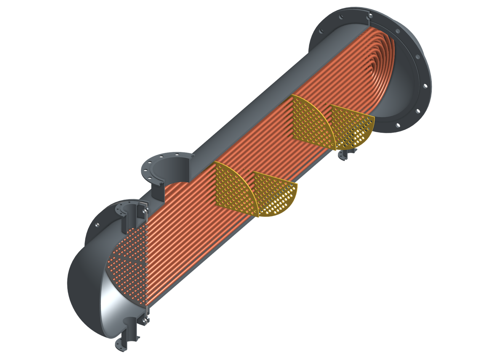
Heat Exchangers
Heat exchangers serve to transfer thermal energy between different process flows. Inside a heat exchanger, a process flow experiences a change in temperature and potentially also a phase transition by evaporation or condensation. There are numerous different types of heat exchangers, and the selection of the most suitable one depends on several factors. During operation, the temperature gradients across a heat exchanger cause uneven thermal expansion of the material, leading to thermal stress. In order to prevent mechanical damage, there are limits for the temperature difference between inlet and outlet of each process flow and also in between the different process flows.
What we can do for you!
We evaluate the relevant operating cases for the sizing of each heat exchanger.
We select the right heat exchanger type for the application.
We define the requirements related to fouling and the corrosion allowance.
We establish measures to ensure that the allowed temperature gradients will not be exceeded.
We create the technical specifications for the procurement of the heat exchangers from external suppliers.
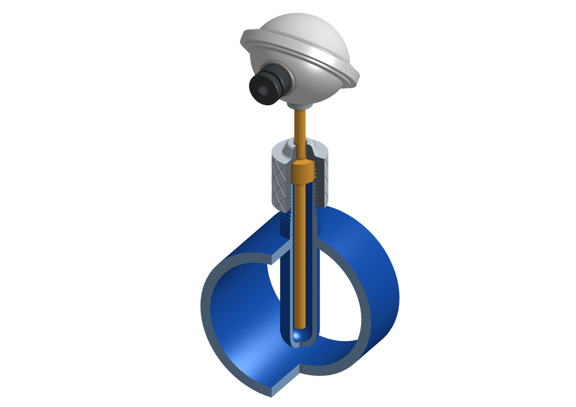
Measurement Instruments
In process plants measurement instruments are used to gather process values in order to monitor and control the operation. The measured values are logged at the DCS (distributed control system) and processed for different purposes such as to control individual components and to start and stop the entire plant or subsystems thereof. The requirements for the reliability of the measurement depend on what it is used for and the possible consequences of faulty values. High requirements can necessitate several independent measurement instruments or the use of specific safety functionalities. Depending on the process value to be gathered the accuracy of the measurement depends among other things on the mounting position of the measurement instrument, the location of the connection relative to the process volume, and, in case of process volumes containing flowing media, the condition of the inlet and outlet sections.
What we can do for you!
We evaluate the relevant operating conditions for the sizing of each measurement instrument.
We ensure that each measurement instrument provides the required accuracy.
For each measurement instrument we define the required mounting position in order to ensure accurate and stable measurement results.
We define for each measurement instrument the routing of the inlet and outlet section as needed for accurate measurement results.
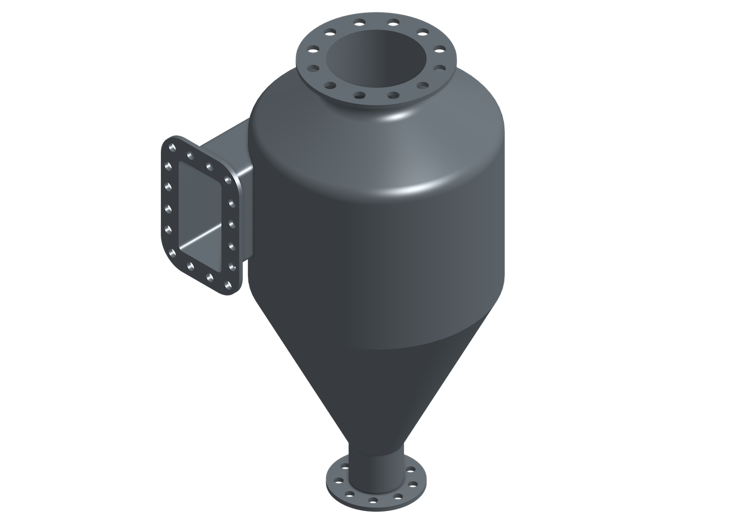
Phase Separators
Phase separators, for example cyclones, are used to separate the phases in a heterogeneous process flow. This can be the removal of solid particles from a gas stream or the separation of liquid and gaseous phase in case of a process flow where the process media is present as vapour as well as in the shape of droplets. The separation happens as a result of the different behaviour of the phases when subject to centrifugal and gravitational forces due to the difference in density. Complete separation of the phases can commonly not be achieved so that traces of the heavier phase remain within the lighter one.
What we can do for you!
We evaluate the relevant operating cases for the sizing of each phase separator.
We define the dimensions required for optimal phase separation.
We create the technical specifications for the procurement of the phase separators from external suppliers.
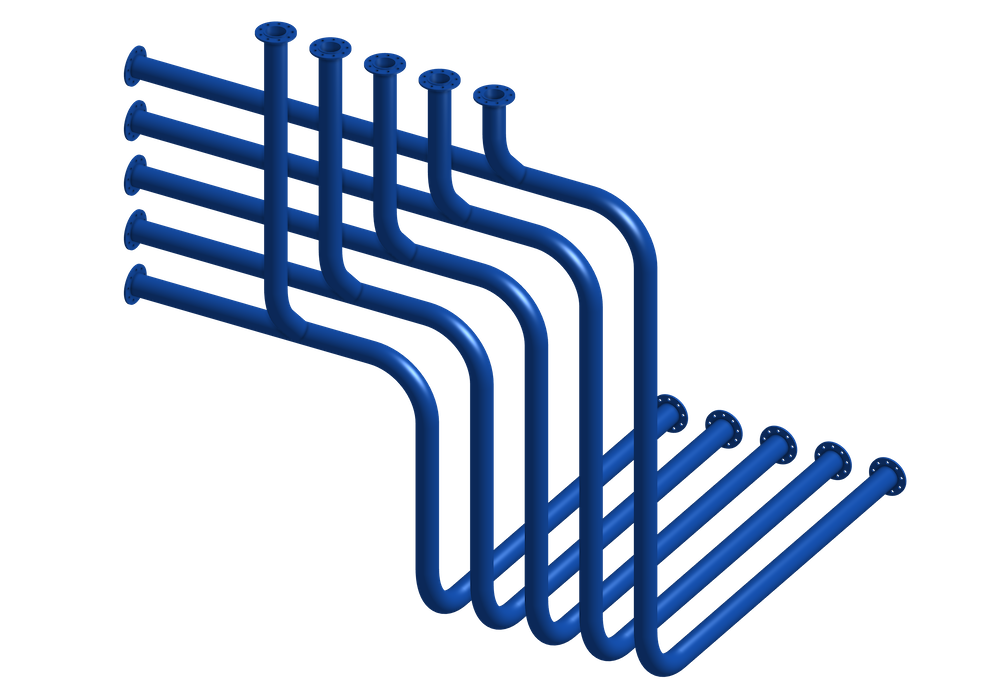
Pipes
Pipes connect the components of a plant, transferring liquid or gaseous media. The transferred media is mostly not meant to undergo any phase changes or chemical transformations while within the pipe. However, phase changes or chemical transformations can still occur inadvertently due to pressure or temperature changes within the pipes, causing harmful effects like increased erosion or pressure hammers. Although most pipes by themselves do not take up much space, the space required by all the pipes of a plant can make up a significant fraction of the overall plant size and must be considered for the arrangement planning from the start.
What we can do for you!
We evaluate the relevant operating cases for the sizing of each pipe.
We examine the pipe routing and ensure that specific process conditions are considered, like hydrostatic pressure differences or the formation of air pockets.
We check the pipes that have to be fabricated in line with the requirements of one of the categories of the pressure equipment directive (PED).
We do pressure loss calculations and select the proper pipe size.
We consider the temperature change of the process flow inside the pipe caused by the heat transfer to and from the ambient air.
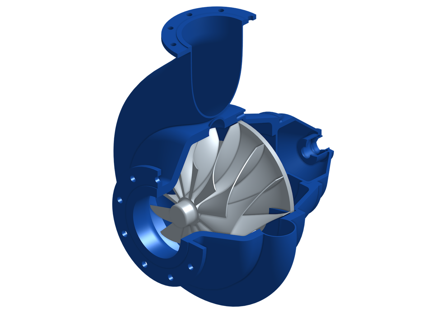
Pumps
A pump creates an increase in pressure which can be used to move liquids via pipes throughout the plant. Pumps are grouped into dynamic pumps and positive displacement pumps. For either type, specific process requirements must be fulfilled to ensure stable and long term operation. Among other things, these requirements include the net positive suction head (NPSH), the minimum and maximum allowed flow rate, and pressure and temperature limits.
What we can do for you!
We evaluate the relevant operating cases for the sizing of each pump.
We select the proper pump type for the application.
We define the required delivery head and flow rate considering all relevant operating cases.
We define measures to fulfill the NPSH and flow rate requirements according to the pump characteristics at all operating conditions.
We create the technical specifications for the procument of the pumps from external suppliers.
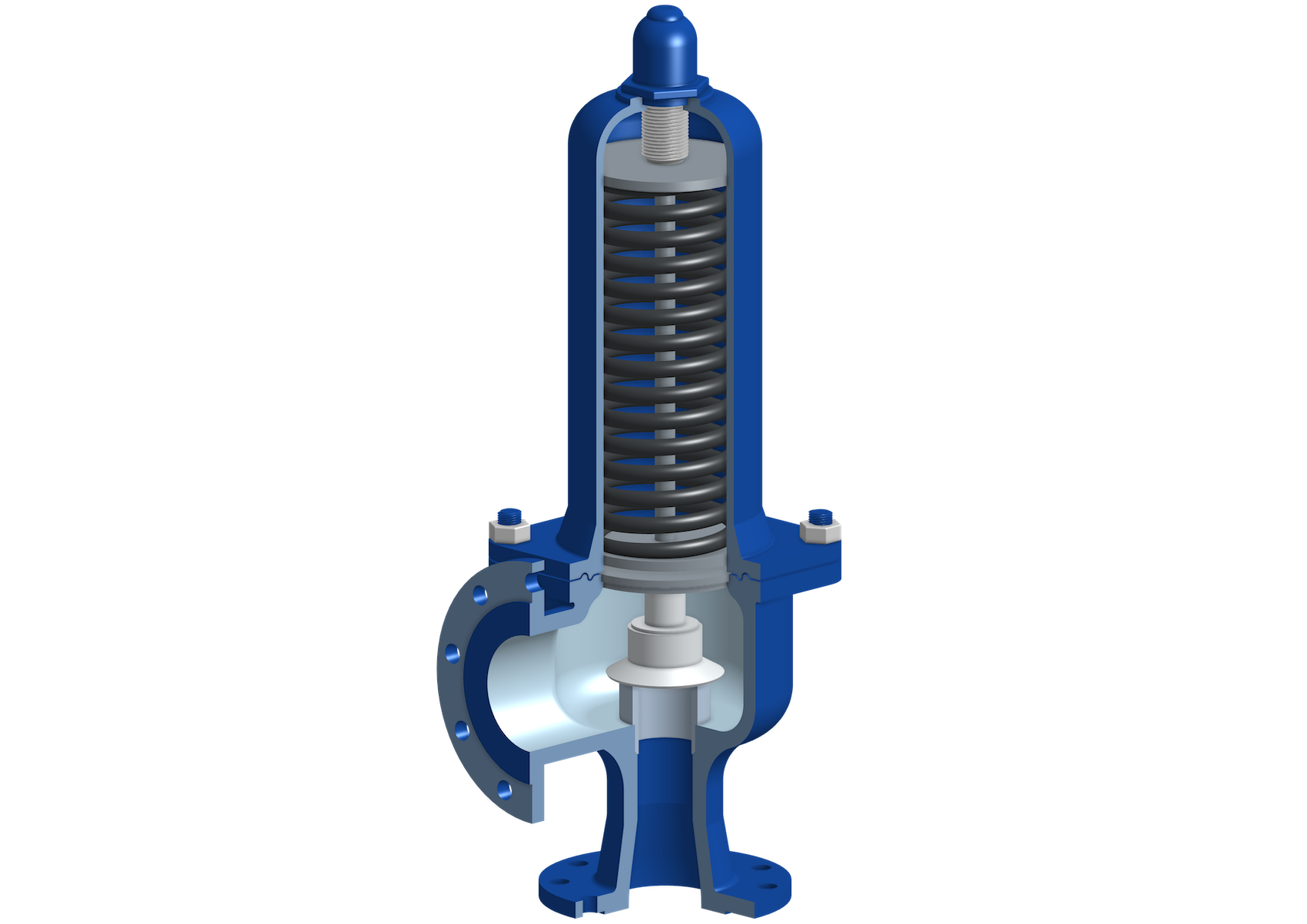
Safety Fittings
In case of faulty operating states safety fittings like safety valves or rupture discs are used to protect the plant against high pressure conditions which would exceed the design pressures of components of the plant. If a certain pressure is reached the safety fittings open to release process medium from the affected process section in order to prevent a further increase of the pressure. Safety fittings are commonly installed at the highest point of the protected process volume so that the hydrostatic pressure needs to be considered when defining the design pressure for components located further below. For the fabrication of safety fittings the conformity assessment procedures according to category IV of the pressure equipment directive 2014/68/EU are applied.
What we can do for you!
We evaluate the relevant operating cases for the sizing of each safety fittings.
We ensure that the pressure losses across the inlet and outlet lines of the safety fittings are within the permitted range and that they are considered for the sizing.
We ensure that the definition of the design pressure of the protected components considers the hydrostatic pressure between the components and the corresponding safety fittings.
We determine the phase relevant for the sizing in case that the process medium is partly liquid and partly gaseous.
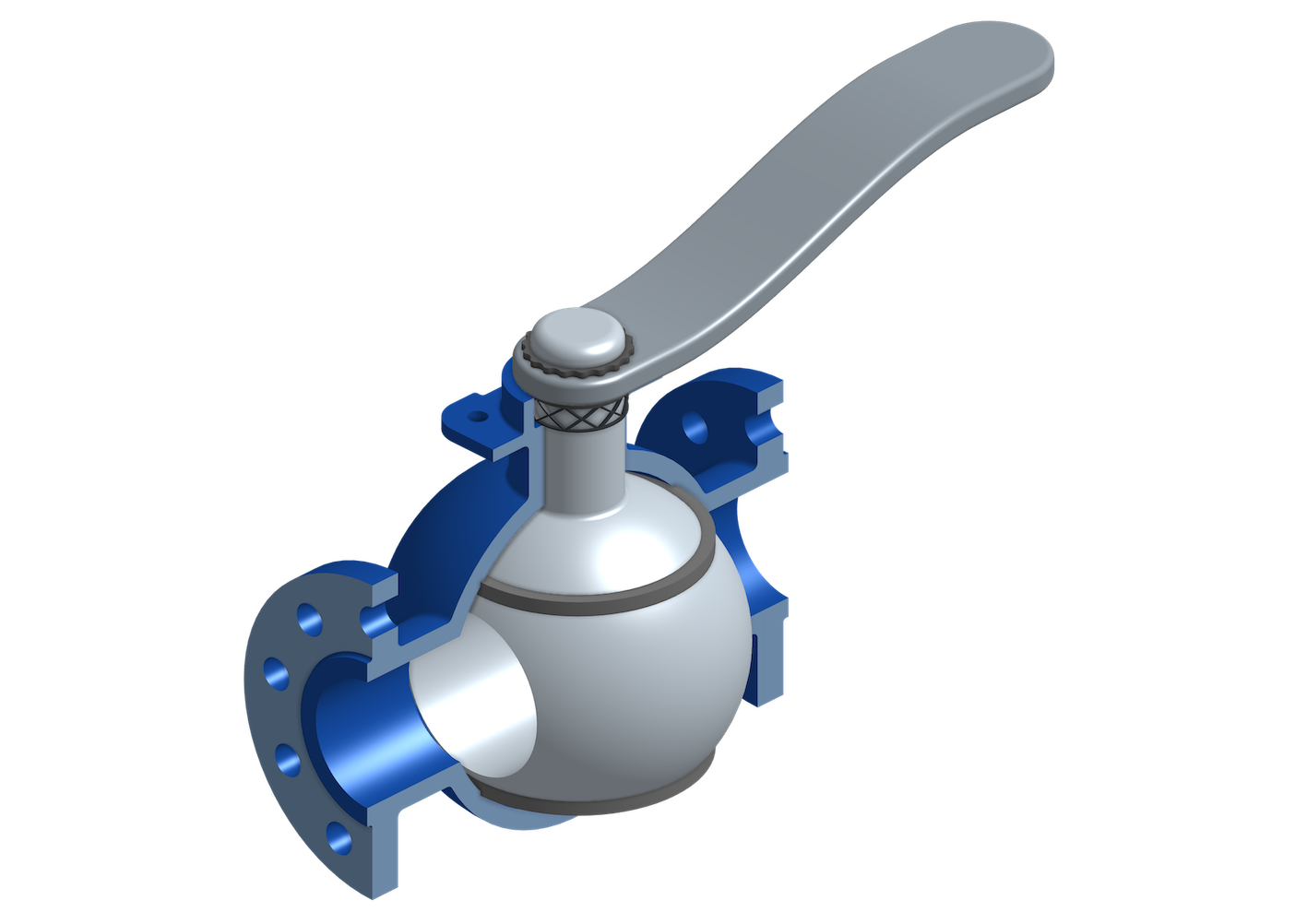
Shut‑Off Valves
Shut-off valves are used to isolate single components or plant sections and to interrupt process flows. As separating elements they facilitate local maintenance and repair works, inspections and retrofits as the separation eliminates the need to shut down the adjacent plant sections. The interruption of a process flow by means of a shut‑off valve is either done as part of the process concept or it is a safety functionality. Shut‑off valves are available in different types such as ball valve, gate valves, or butterfly valves. Which type is suitable depends on the pressure and temperature requirements, the permitted pressure losses, as well as on the quality of the process media.
What we can do for you!
We evaluate the relevant operating cases for the sizing of each shut‑off valve.
We select the proper valve type for the application.
We identify the required Kvs-value.
We create the technical specifications for the procurement of the shut‑off valves from external suppliers.
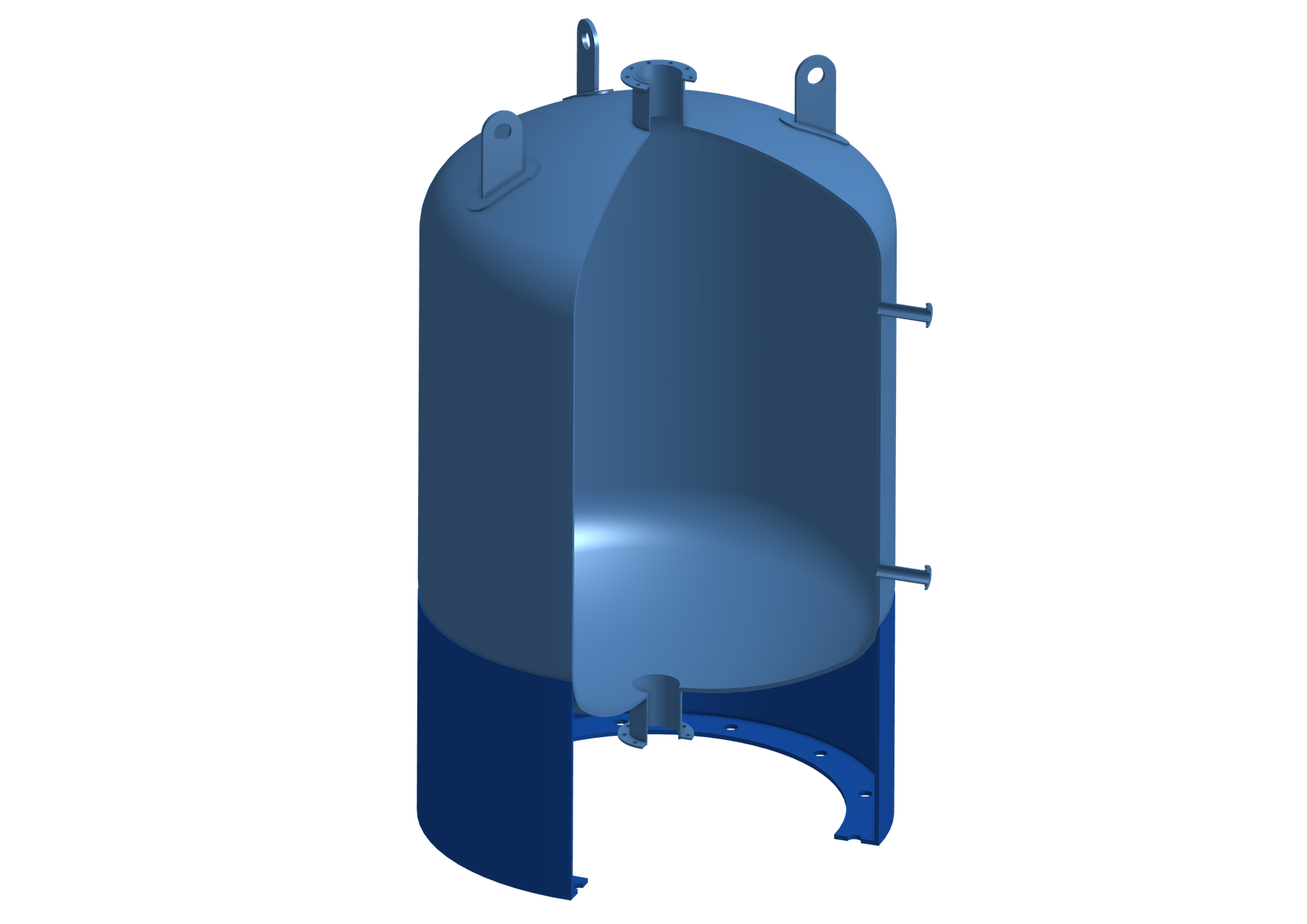
Vessels
A vessel is any type of container to hold liquid or gaseous media. Vessels are used for various purposes inside a process plant. They are integrated into the process to receive and release process media, or they provide long term storage capacity for process utilities. The purpose of a vessel will not only define its size, material, and design parameters, but it will also have to be considered to define its shape and the position of the inlet and outlet connections.
What we can do for you!
We evaluate the relevant operating cases for the sizing of each vessel.
We define location and size of all connection ports of the vessel including connection ports for ingoing and outgoing process flows as well as connection ports for instrumentation.
We define the required construction material for the vessels to ensure mechanical longevity and to prevent contamination of the process media.
We create the technical specifications for the procurement of the vessels from external suppliers.